Earlier this week I scrounged around online for SCCA safety cage standards and found this PDF. The information was not only interesting, it was intensely helpful. But before I get into all of that, though, let me say this. It is not my intention to follow the every letter of this standard. I’m simply using it as a guide.
It’s a lot of spec to pour through for the casual reader, so here are the highlights as they pertain to this project.
- Must be of one of two designs: A high roll hoop (over the windshield), or low roll hoop (over the steering wheel).
- Must be protect from roll over, impact with an obstacle, and impact from another car.
- Must be able to support the weight of the vehicle if overturned
- Must be able to withstand the forces withstood should the vehicle go sliding on the cage
- Head restraint is mandatory and must prevent whiplash as well as prevent the driver’s head from striking the main roll hoop. Depending on what seat you use, the head restraint may or may not be required to be physically tied into main hoop.
- Any forward bracing from the main hoop must be padded if the driver’s head is able to contact it.
- Neither the cage nor the chassis can have an aerodynamic effect that creates lift.
- The cage must prevent engine intrusion into the driver compartment.
- Minimum tubing sizes for mild steel for vehicles under 1500 lbs: 1.375″ x .095″
- The main hoop must be one continuous piece of steel, can have no more than four bends, those bends cannot total more than 180º, and the radius of those bends must be more than 3x the diameter of the tubing
- The front hoop must also have no more than four bends
- Rear hoop supports (cross bracing) must be straight
- The rear hoop, if possible, should go all the way to the floor and all joints should be reinforced by gussets or sheet metal webbing
- The main hoop must have at least two braces extending to the rear, and two to the front, attached no more than 6″ from the top of the hoop, with an angle of at least 30º
- The front hoop requires two braces to protect the driver’s legs
- Side protection should include at least two tubes connecting the front and rear hoops across all door openings
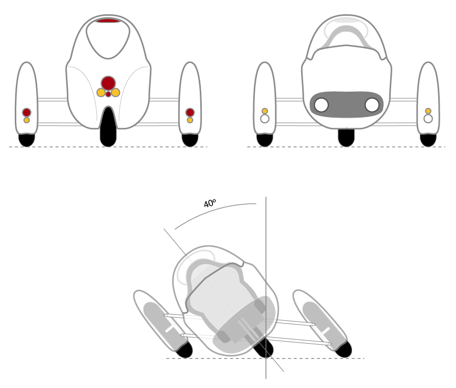
- The roll bar must be able to withstand stress loading of 1.5x laterally, 5.5x longitudinally, and 7.5x vertically where x is the minimum weight of the car.
- The race seat must be firmly mounted to the frame, and the back of the seat must be tied into the main hoop or its cross bracing unless the seat is specifically designed to be unbraced.
- The main hoop cannot be less that two inches above the driver’s head
- A straight line drawn from the top of the main hoop to the top of the front must pass over the driver’s head.
- The main hoop must be at least 15 inches wide where attached
There’s a lot there, but there are a couple of things that had a really profound effect on my design. The first is the minimum tubing size of 1.375″. I’d been doing all my weight calculations on 1.675″ tubing and by scaling down to this standard, the estimated weight of my safety cage goes from about 130 lbs to about 80 lbs. That’s a huge difference, especially for a vehicle this light and with the efficiency ambitions that I have. So that’s a win.
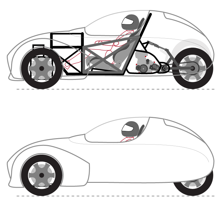
The second significant standard wasn’t so kind. It’s this one:
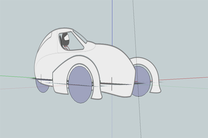
A straight line drawn from the top of the main hoop to the top of the front must pass over the driver’s head.
Here’s what that looks like in my current design:

The problem here is obvious. I’m less concerned about the standard itself than what the standard is meant to prevent. Namely, the vehicle landing on my head. There are really only two solutions to this, at least that I can think of. Either both the front and rear hoops get taller (which kills my streamlining and visibility), or I’m going to have to brace across that gap in a way that clears my head. So I took a page out of the off road buggy book an designed a pair of curved A-pillars to connect the front and rear hoops.

What I’ve rendered here is incomplete, in the sense that there will be a lot more cross bracing than is currently showing. For simplicity’s sake, I’ve kept this rendering to just the main hoops and cross members (plus the door). This change doesn’t really have any impact on the body shape or my aerodynamics, thankfully.

What these new A-pillars do effect, however, is the canopy design and entry/exit. While the struts themselves may indeed bolt in and out in the end, they won’t swing over with the canopy as it previously worked. In fact the whole removable canopy idea is kind of out the window at this point, I think. Instead, there will likely be more of a t-top arrangement where the side windows and perhaps part of the roof are removed and stowed. That, or perhaps just go Jeep-style and do zip-out covers that are heavy canvas or nylon with polycarbonate windows suspended in the fabric. This does afford an opportunity for an elegant permanent windshield, however. By curving the A-pillars in as well as up, that compound curve (which will be a bitch to fabricate, but worth it), should make getting in and out (via the door) easy as any normal car, if not easier. And at just over an inch in diameter, they shouldn’t impede my visibility. While perhaps not as mean looking as the full canopy was, this new design is mean looking in a different way, and a whole lot safer. I’ll take that.