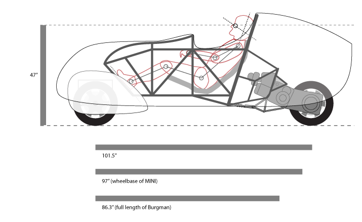
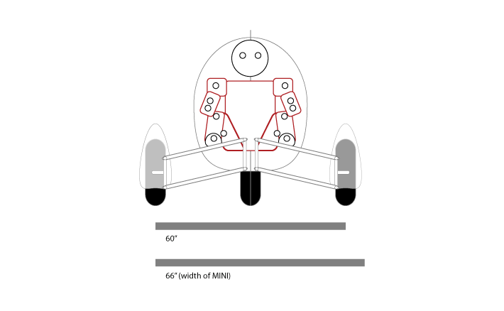
Tonight I’ve done some further playing in Illustrator to try to flush out the reality of the Streetliner’s real world dimensions as I’ve envisioned it. What I found is surprising, namely in just how much bigger the vehicle is than I imagined. Like many of yesterday’s discoveries, it’s a pretty big “duh” once I step back and think about it. If I move the motor back and place the driver in a long, recumbent position, then I’m going to end up with a vehicle quite a bit longer than its Bergman donor. Observe:
The driver representation is calibrated to my height, and I’ve even been able to reproduce the Bergman powerplant close enough for this kind of ballpark purpose — including some of the Bergman sub-frame for the engine mount. I was pretty surprised to find that by bringing the driver down and leaning the seating position back into an ergonomically correct position it added about 40″ to the overall length. That got me thinking, how would this vehicle compare size wise to say, my MINI Cooper S? Turns out, the Streetliner in this configuration would be roughly the same length as my MINI hatch. I discovered yesterday that in picking up the body relative to the wheels, it put my eye height at roughly the same height of my MINI as well.
The MINI makes a very convenient measuring stick for me because it’s not only a small car by normal, American standards, but I drive one almost every day. In a lot of ways I feel like the MINI is about as small as a car can be before it starts getting hard to see by other drivers. I’m used to driving hyper-defensively from riding my Vespa, but it’d be nice to be that much more visible all the same. It was a surprise though, to see that the Streetliner in this configuration would indeed be a bit longer than my MINI and only a few inches narrower in track.
It’s important to remember that the width of the actual vehicle body will be about half that of my MINI and much more aerodynamically shaped. This should present perhaps as little as a third of the frontal area to the resisting wind. Combine that with this vehicle weighing less than 25% what my MINI does, and likely using an engine with about 25% the displacement and funny enough, 25% the horsepower. That should make for impressive mpg gains without even touching the engine gearing. All while likely retaining a top speed of around 100 mph.
It’s exciting stuff. I also started mocking up the basic configuration of the safety cage/chassis, but that’s another post all together.


One further realization was that my up-front trunk idea just isn’t going to work at all. Thankfully though, there’s still a lot of room in the tail. Plenty for groceries or even a small duffle bag. If there develops a bigger luggage requirement, I could always fit GIVI motorcycle cases somewhere on the sides, even behind the wheels, like they do on the T-Rex.
Pictures like these would be a great place to start estimating Center of Gravity placement. You made a comment in another post about how wide the front wheels will need to be to prevent it from tipping over when stationary. But on a trike there’s no way you can tell how wide that is without knowing where the CoG is.
You can get a pretty good rough guess just by looking at the heaviest parts of the trike, that being the chassis, wheels, engine, and the driver. The chassis CoG should be pretty close to the middle, both horizontally and vertically. The CoG of the three wheels should be at the axle height and 1/3 of the way back along the trike centerline from the front tires to the rear tire (if all 3 are the same size). The engine is small and dense enough that you can estimate the CoG to be in the middle of its outline from any view. And the CoG of a recumbent human is a couple inches in front of his navel if I recall.
Once you have all of those, the combined CoG is easy to find. Draw a line between the CoG of any two parts, and the combined CoG divides that line in the same fractions as the relative weights of the two parts. So for the wheels for instance, the combined CoG of the front two wheels is on the vehicle centerline halfway between them (because they both weigh 50% of the combined weight). Then connecting that point with the CoG of the rear wheel, the combined CoG of all 3 cuts that line in 1/3 – 2/3 (short segment near the front) because the front pair is 2/3 of the total weight of all the wheels together. Just continue that process adding the weight of the chassis, engine, and driver to the increasing total and you’ll have a pretty good idea where the CoG will end up, and how wide the front wheels need to be to maintain your design goal.
Wow. Thanks for that, Aaron. I’m familiar with the principles, but that’s a great break down with some details I didn’t know before. I also realize that the most important thing is that the horizontal CG be above the axis of tilt rotation. Otherwise tilting is going to throw weight to the outside of the turn and that’s just a mess. Adding some height to the vehicle helps that instantly.
A couple of points that you might find particularly interesting. If you look at the motor swing arm there’s a triangle of sub frame with a circle in it. That is actually the pivot point of the assembly. The engine and intake are on one side and the transmission/brake/wheel on the other. I don’t know for sure, but I’d wager that the pivot point is pretty close to the actual CG of that assembly so as to help offset the unsprung weight of the whole unit and improve handling. This would make sense from a mass standpoint as well because the transmission is actually mostly empty space, but a longer lever. I had a 150cc scooter last year with a rear-end like this and in fact most modern scooters now use the engine as a counterweight to at least some extent. It makes a huge difference when compared to the vintage bikes where the motor, transmission, and everything all hung rear of the pivot bolt.
As for the CG of the frame, I haven’t even begun to think about that. The frame in this illustration is just thrown in there and not at all thought through. I did, however, do some rough length estimates and ran that through a weight calculator online and it came back at right around 150 lbs for the tubing of the main safety cage. That didn’t include the front suspension subframe or the engine subframe, but in relative terms, those are less steel and made of smaller diameter stuff. But even with those, the weight of the main vehicle structure could be less than 300 lbs. It’s amazing how tubing diameter has such an exponential relationship to weight. Although, all of that is without doing any of the actual structure study and engineering that will need to go into the final cage/chassis design. I do think though, that less substantial sub frames front and rear would essentially act as “crumple zones” in the event of an impact. That’s good stuff. Mount them on a down angle, and they’ll naturally submarine under the passenger compartment as they come apart and absorb impact energy. None of that has anything to do with CG yet, but it’s all progress.
Thanks for contributing!