Scale sizes for brass tubing

I’m currently collecting parts and materials for a small-scale functional prototype. I’ll be using 6″ diameter wheels up front and from that I’ve been scaling down dimensions from my design graphics to match that proportion. Presently, my small-scale prototype will be 22% the size of the real deal. That’s not quite quarter scale, and should be plenty big enough for me to build most components in about the same way they’d be built in full size. If I also scale my materials as much as possible, it’ll give at least some idea of structural rigidity (although not material rigidity). More importantly it’ll hopefully reveal the majority of mechanical complications. I’m going to use brass tubing because it’s inexpensive, readily available, and I can solder it together similarly to how I’d weld the real thing out of steel. I can also easily bend curves and other complex shapes without too much effort

So at 22% scale, my equivalent brass tubing sizes are as follows:

1″ steel tubing (the majority of the structure) = 7/32″ brass tubing [rounding to 1/4″]

1-3/4″ steel tubing (the heavy bits of the roll cate) = 3/8″ brass tubing

1/4″ steel plate = 1/16″ brass plate

These materials should be lightweight enough to be easily workable. Once it’s all soldered together, it ought to be pretty sturdy. I’ll be able to find small bearings, bushings, and other hardware at the local R/C car shop. Now that I have both a working band saw and a drill press, I should be able to fabricate pretty much anything at that scale. I wonder if I could even mill parts on my dremel press from solid brass if I take small bites. We’ll see.

Surprising weight

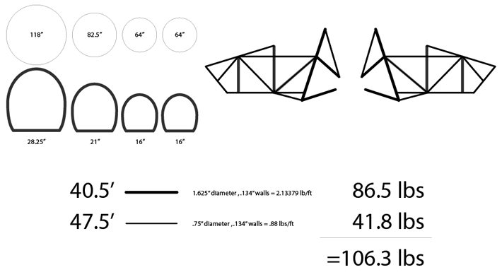
I’ve refined my safety cage a bit and done some more research into safety cages used in racing. I found a kit that featured 1.75″ tubing with .135″ thick walls. Running that through the online weight calculator I’d found, that comes out to 2.133 lb/ft. I also did a calculation on 3/4″ tubing of the same wall thickness for use in cross ties and such. Figuring out the length of the tubing in this design, I was able to do some weight calculations:

This is all obviously napkin math, but the result is pretty surprising. If I use the 1-3/4″ tubing for the main structural hoops, then tie it all together with 3/4″ tubing, my entire safety cage and main chassis would only weigh about 100 lbs 130 lbs. This doesn’t include some sub-frame pieces and none of the front suspension components, but still, that puts me well on my way, I think, toward making my < 600 lb design criteria.

Wheel size, wheel pants, stability and leverage

They were apparently absolute murder to ride, but nothing quite says vintage transportation like the Velocipede. The thing I’ve always found fascinating about these is their huge front wheels. The physics of a bike like this must feel very odd compared to bicycles of today. The force of angular momentum of a wheel (the force that makes it want to stay upright and that leans it when you top turn it) is directly proportional to the torque moment of that wheel. Or, said in non physics babble, the bigger and/or heavier a wheel is, the more stable it is when its rolling. It’s kind of an amazing force, when you think about it. The two tiny rollerblade-like wheels of a little razor scooter generate enough angular momentum to hold an adult upright. In larger, powered two-wheelers like scooters and motorcycles, wheel size makes a huge difference in the character of the machine. Scooters have traditionally had much smaller wheels. Most vintage small-frame Vespas had only 8″ rims, while their large frame brothers weren’t much larger at 10″. My modern Vespa has 12″ wheels, but still feels very much like a scooter — agile, and a tad butt-heavy. Motorcycles tend to have anywhere from 14″ to 22″ rims depending on the style. When I test rode a Triumph Bonneville in 2008, what I noticed immediately was that it took about half the speed I was used to in order to get rolling stability. Once moving, the larger wheels and rolling mass of the Bonneville felt so solid — like it was on rails. What would wheel size mean for the Streetliner?

Bigger front wheels
While playing with the proportions and broad strokes design details of the Streetliner this week, I wondered what would happen if I swapped out Burgman-size front wheels for larger wheels from another bike in the Suzuki fleet. The size of the rear wheel is likely fixed because of the shape of the engine/transmission casings. Big wheels up front would definitely give it a stronger visual connection to the old race car designs that have inspired the project. Especially if I grabbed the spoked wheels off of something like the Boulevard S40. But beyond aesthetics, it would make some significant differences to handling comfort, lean feel, and possibly even make the front suspension easier to build. It looks the business though, doesn’t it?

That’s an 18″ rim up front as opposed to the 14″ stock Bergman rim on the rear. It definitely calls back some nostalgic racing mojo. Larger diameter wheels would mean that the front end would take bumps better and have greater rolling stability. It’ll also mean more room inside that wheel for all the tilting mechanicals, brakes, and steering attachments. What it would also mean is that the lower and upper swing arms of the tilting suspension could be further apart — letting me have not only better ground clearance, but deeper leaning on the same distance between the wheels.

If you go back to my initial lean study, I explored the relationship between body height and leaning. With the larger wheel size up front, a couple of good things happen. First, I’m able to spread the swing arms apart, meaning that at the same lean angle, there’s less interference. This is important at both the wheel attachment points and where the dampening assembly will go (the shocks and their connecting structure, which isn’t shown). The more room there is to work in those assemblies, the better. Not only will it be easier to build, but it’ll mean more opportunity for building fine tuning and adjustment points right into the structure.

Stability
The biggest difference may indeed be felt in leaning stability. The greater mass of those larger wheels would mean nearly instant leaning stability. Whenever I see a Honda Goldwing slowly lean its way through an intersection turn, it amazes me that the 900 lbs or so of the Goldwing are able to be held up at such low speeds. The Goldwing has an 18″ wheel up front and a 16″ wheel in the rear, and that’s enough to keep it stable, even at low speeds. With two 18″ wheels up front, the leaning stability ought to be massive. But more than that, having the swing arms further apart vertically, means that the side-to-side forces generated by the wheels when they precess (based on steering input) will not only be greater, but have more leverage on the body of the vehicle.

The one thing I wonder about, however, is what it will do to the driving feel of the vehicle? Greater stability means that it will take more input force on the steering to induce the lean — and that force will grow with speed. That’s a good thing, as you wouldn’t want the vehicle to be all twitchy at 70 mph. I’m not worried about it, I just wonder what the feel will be. I imagine it wouldn’t be much different than a big cruiser motorcycle with the Tilting Motor Works kit installed.

Wheel pants
From the beginning, I’ve envisioned the Streetliner with wheel pants for added aerodynamics and efficiency. This inspired by both ’30s era aircraft like the Gee Bee but also similar projects like the Aptera. Exposed wheels simply aren’t very aerodynamic. Putting a streamlined shroud around the wheels will add effeciency (and look fantastic). However, I’m not exactly sure just how much efficiency is gained. Adding wheel pants will definitely add time and complexity to the build, and at some point I’m going to have to do an aerodynamics study to see how much more efficient the shrouded wheel is than a naked wheel. One thing I have to keep in mind though, is that unless I can put a decent tail on the pants, there won’t be much advantage in the wind. However, that tail will quickly limit how far I can turn the wheels (because the tail of the pants will hit the body). That means a large turning radius, and for a vehicle intended for mostly city use, that’s not a good thing. So if I have to sacrifice wheel pants for the sake of turning ability, that’s a compromise I can’t not make. But I do just love the look of the pants. I hope I get to keep them.


Surprised by size

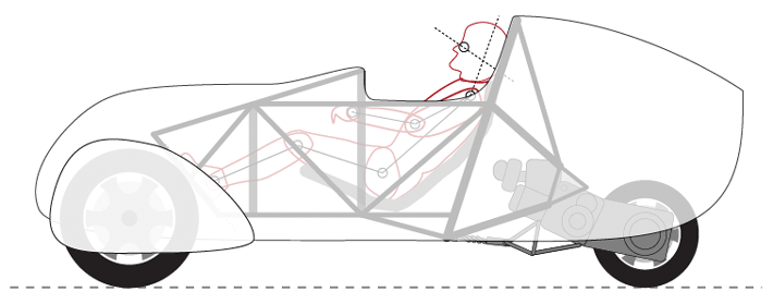
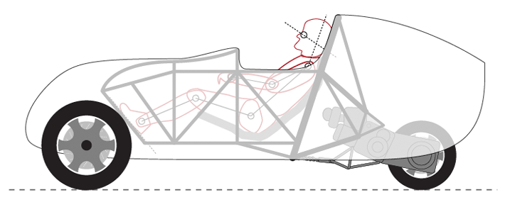
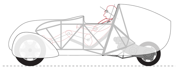
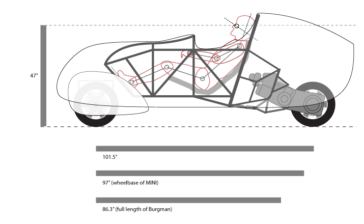
Tonight I’ve done some further playing in Illustrator to try to flush out the reality of the Streetliner’s real world dimensions as I’ve envisioned it. What I found is surprising, namely in just how much bigger the vehicle is than I imagined. Like many of yesterday’s discoveries, it’s a pretty big “duh” once I step back and think about it. If I move the motor back and place the driver in a long, recumbent position, then I’m going to end up with a vehicle quite a bit longer than its Bergman donor. Observe:

The driver representation is calibrated to my height, and I’ve even been able to reproduce the Bergman powerplant close enough for this kind of ballpark purpose — including some of the Bergman sub-frame for the engine mount. I was pretty surprised to find that by bringing the driver down and leaning the seating position back into an ergonomically correct position it added about 40″ to the overall length. That got me thinking, how would this vehicle compare size wise to say, my MINI Cooper S? Turns out, the Streetliner in this configuration would be roughly the same length as my MINI hatch. I discovered yesterday that in picking up the body relative to the wheels, it put my eye height at roughly the same height of my MINI as well.

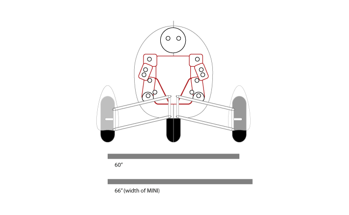
The MINI makes a very convenient measuring stick for me because it’s not only a small car by normal, American standards, but I drive one almost every day. In a lot of ways I feel like the MINI is about as small as a car can be before it starts getting hard to see by other drivers. I’m used to driving hyper-defensively from riding my Vespa, but it’d be nice to be that much more visible all the same. It was a surprise though, to see that the Streetliner in this configuration would indeed be a bit longer than my MINI and only a few inches narrower in track.

It’s important to remember that the width of the actual vehicle body will be about half that of my MINI and much more aerodynamically shaped. This should present perhaps as little as a third of the frontal area to the resisting wind. Combine that with this vehicle weighing less than 25% what my MINI does, and likely using an engine with about 25% the displacement and funny enough, 25% the horsepower. That should make for impressive mpg gains without even touching the engine gearing. All while likely retaining a top speed of around 100 mph.

It’s exciting stuff. I also started mocking up the basic configuration of the safety cage/chassis, but that’s another post all together.


Body height to lean angle study

With the broadest strokes of the exterior design penned as far as is practical at this point, it’s time to do some real work. Up to now, I’ve pretty much just eye-balled it. With the pieces starting to come together, it’s time to get more specific and more precise. So today I explored the relationship between body ground clearance and tilt geometry. There are a lot of factors effected by this relationship. Some I anticipated, some I didn’t.

The major factors are these:

  • Lean angle
  • Ground clearance
  • Center-of-gravity shift
  • Eye height of the driver

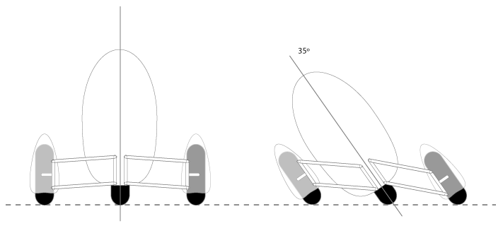
Tilting Study A
Tilt_Study_A

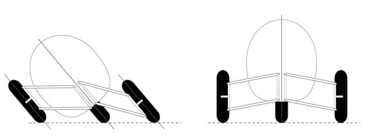
I started with a low profile body height that would keep the suspension swing arms essentially level. From studying the Brudeli Leanster, it looks like so long as the swing arms are parallel, they need not actually be level. This makes sense as I start to lean the elements visually. One of the things I was most curious about was the relationship between body height and maximum practical lean angle. Tilting things over in Illustrator, it looked like 35º was about all I was going to get before bodywork was likely to start scraping. My first surprise was how far the rear wheel slid right, which made instant sense, but was unexpected. It’s exciting to see just how far over that body swings from centerline — pushing the center of gravity deep into the apex of the turn. Given that it’s nearly impossible to low-side a tilting trike, moving that much mass to the center of the turn has me pretty jazzed thinking about the cornering capabilities of a vehicle like this. My one hesitation is in line-of-sight. Sitting too low is a major safety concern.

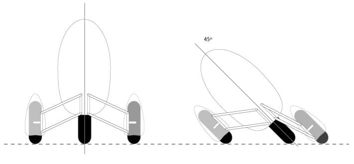
Tilting Study B
Tilt_Study_B

So what happens if the body gets picked up quite a bit higher than the wheels? Using the same length swing arms, this obviously brought the front wheels in tighter to the body. The end track of the vehicle is yet to be determined, and it’s not as though the swing arms can’t be lengthened if needed. I was again surprised at just how far the rear wheel swings from side to side. A deeper lean angle of 45º seems likely in this arrangement. 45º is considered the standard of a deep lean, as this is the depth to which sport bikes are able to lean — their riders laying padded knees into the asphalt. In essence, this is what having two wheels up front does for the Streetliner. There is an issue with this kind of arrangement, however. A closer examination of the swing arm attachment makes it look pretty obvious that unless I bend the ends of the swing arms, they’re going to interfere with the outside wheel. Also, if the body is too high, then I’ll need a really wide track to meet one of my minor design criteria — that leaned fully over, the vehicle will not actually tip over and fall if not moving. With no ability to put my feet down, this little detail is crucial. On the positive, it’d mean a nice high line-of-sight. It would seem prudent to find something in between.

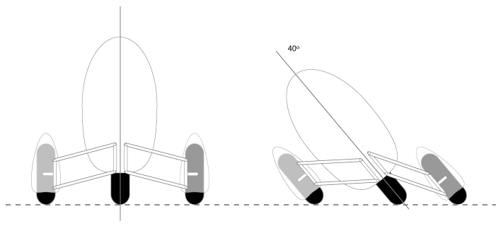
Tilting Study C
Tilt_Study_C

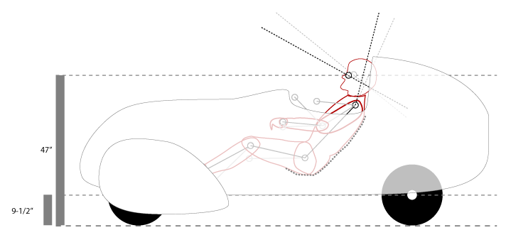
In splitting the difference, I found a nifty elegance. By aligning the bottom of the body with essentially the axle height, I think I’ve found the sweet spot. 40º seemed easy with only the wheel pant in danger of interference. I bet 45º would be possible depending on the engine and transmission casings.  With further study and measuring, this configuration yields an eye height of approximately 47″. This puts it almost exactly where my line-of-sight is in my MINI, which is actually very good. But more exciting is as much as 9″ of ground clearance. That should make for both very clean aerodynamics and easy road going over fairly substantial road hazards.

Tilt_Study_eyeline

Obviously, this is all just estimation, but it’s been a fascinating thought experiment. It’s also yielded a deeper understanding of seating ergonomics, but that’s for another post.

Two more nifty trikes

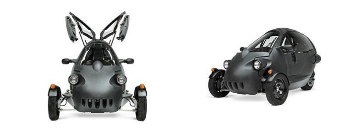
The Cree SAM

feature_otherTrike01

Via Diseno-art.com:

The Cree SAM is a product of Swiss company Cree Ltd. The SAM is an environmentally friendly zero emissions vehicle powered by an electric motor. Only 80 Cree SAM’s have been produced so far, and most were bought by private consumers for public testing in Switzerland.

The electric motor of the Cree SAM is capable of propelling the 3-wheeler up to 53 mph (85 km/h). And on a full charge the SAM has a range of 30 – 45 miles (50 -70 kilometers).

The lightweight Cree SAM is built on an extruded aluminum chassis, and the two occupants, seated in tandem, are protected by the air-filled, double wall, thermoplastic body.

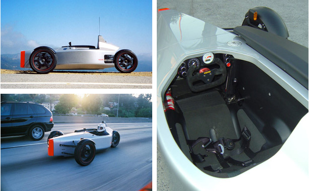
The SUB G1

feature_otherTrike02

Also via Diseno-art.com:

The SUB G1 is a 3 wheeled sports vehicle which was first unveiled in April 2005. SUB is a small company based in Southern California run by three design professionals with impressive resumes, and between them the skills to design, model, engineer, and construct, high quality production machines like the SUB G1.

The G1 is a development of a similar concept vehicle (the 1up) created by one of the group, Niki Smart, years earlier. Smart, along with Jay Brett, an industrial designer with experience in constructing concept vehicles for films, and Nick Mynott, a digital modeller with experience in race and concept car construction, decided to develop an attractive, single seat, high performance sports vehicle, specifically designed for entertaining handling and extreme fun.

So far, three SUB G1’s have been built and handed over to their owners, 2 in the US and one in the UK, and each has covered over 1000 miles, with no problems.

One of the most noticeable features of the G1 is the outstanding build quality and level of professionalism visible in the overall design. Each part, down to the nuts and bolts, has been well thought out and made to fit with the finished product. By using computer models, the team was able to digitally create and adjust components before manufacturing, therefore reducing costs and unforeseen construction problems.

Power for the SUB G1 comes from a 1000cc Suzuki V-Twin taken from the Suzuki TL1000R sportsbike. The group had originally envisaged an inline 4 cylinder taken from the Yamaha R1, however early on in the mockup stages the group realised they would run into some packaging issues which would upset the 50/50 weight distribution, and the layout they wanted. The Suzuki V-twin fits perfectly, and is mounted to the right of the driver in its own compartment. Developing 135 horsepower and 105 Nm of torque, the engine is force-fed by the noticeable snorkel sitting above the bodywork. Transmission is handled by a 6 speed sequential gearbox connected to the rear wheel by a chain. Current prototypes have no reverse at the moment. But then again, if you’re to lazy to get out and push the diminutive G1 a couple yards it’s probably not your type of vehicle. The instrument gauges also come from Suzuki, and the cutoff sports steering wheel can be removed to ease entry and exit – while also providing a simple security device, if you take it with you.

Some thoughts on reverse

This vehicle exists in sort of a strange place in-between being a car and a motorcycle. It will lean like a motorcycle and utilize big scooter mechanicals, but it will also be enclosed like a car. There will be no need to put my feet down at intersections, because a simple on-demand locking system on the tilting suspension will allow the vehicle to stand on its own three wheels (which will also remove the need for a side or center stand). Being enclosed will mean both comfort, aerodynamic efficiency, and actually a large amount of safety. There really is a lot of elegant convergence here. The locking tilt actually enables me to never need to put my feet down, which makes enclosing the vehicle easier with no need for holes or “bomb bay doors” to pass my feet through. What I have yet to figure out, however, is how to back up.

You simply can’t not have reverse. Sure, most motorcycles / scooters don’t have a reverse gear, but you still have to “walk” them backwards to get out of parking spaces and other common driving situations. Some large motorcycles such as the Honda Goldwing do have actual reverse mechanisms, as do electric bikes like the Vectrix that use their hub motor for regenerative braking. But so far, I haven’t been able to locate a scooter in the 400-600cc range that includes a reverse gear. This year’s Honda Silverwing info says the following:

The V-Matic means no shifting, ever—not even into Neutral or Reverse.

This would seem promising, but a phone call to my local Honda dealer confirms that this is in fact just really, really bad marketing copy. So I’m at a bit of an impasse. Reverse is a must, but I can’t find it built-in to any of the powerplants I’m considering for this project. So I’ve got to figure this out.

Electric option #1: Hub motors in the front wheels
There are a couple of ways that I could utilize electric motors for reverse. One route would be to use hub motors in the front wheels and essentially make an electric hybrid. Piaggio has a hybrid version of the MP3 that does exactly that. Front hub motors would make regenerative braking available, and with that, reverse. The major, and in my opinion, irrevocable barrier to this option is its complexity and its expense. I’d likely have to purchase those hub motors directly from Piaggio and they wouldn’t come cheap. Then there’s the batteries, which add significant weight, and the added complexity of all the speed controllers and power management systems it would take to link the motors to the throttle and balance them against the IC engine. As cool as a hybrid would be, it’s an awful long way to go just for reverse.

Electric option #2: Drive the rear wheel on either direct friction, a sprocket, or a clutch
There are a number of electric and IC engine kits out there for motorizing bicycles. Many of these involve a friction roller that contacts the rear tire. Although probably not the most elegant solution, something similar could work very well. A small, high-torque motor like a wheel chair motor or a even an ATV winch motor could be suspended from a subframe that could be lowered against the rear wheel to turn it backwards. I’m picturing something like a hand-brake lever with a trigger button on it to run the motor. The Lightstar Pulse used a similar system, except that they used an aluminum cone pushed against the wheel rim instead of a rubber wheel on the tire. Online owners report that it’s adequate, although very slow and apparently a massive battery drain. I was already planning to run a significantly larger battery than would be standard in a scooter in order to support a handful of ancillary electronics, so perhaps that would be enough, presuming the bike’s stock charging system can replenish it.

One related idea I had in this vein would be to use a sprocket on the wheel that the motor could engage with its own toothed gear. Perhaps a starter motor/solenoid system would work. Apparently the Honda Goldwing uses a reversible starter motor for its reversing functions, albeit at the flywheel. The one thing I wonder about would be the wear and tear of that kind of engagement. As for the sprocket, I was thinking that I could just have teeth put on the rear brake rotor. It’d mean a bit of precision bracketry, but may indeed be the ideal arrangement.

The third variation would be to use a belt or chain drive between a motor and a sprocket/pulley on the rear wheel and be able to engage a clutch on that mechanism. Depending on how it was set up, it could even double as a low-speed charging system to recoup some of the energy used in backing out of a parking space.

Manual option #1: The Fred Flintstone method
Most velomobile trikes have a pair of holes in the bottom of them to allow the rider to back up under foot power.  This could work for the Streetliner, presuming I have enough leverage to scoot the weight from a seated position. Having a pair of permanent holes in the underside of the vehicle does not appeal to me at all. Nor does having some sort of door/hatch system. This thing is complicated enough. Although, I have to admit, there is an elegance to just hoofing it.

Manual option #2: Some sort of crank to the rear wheel
Perhaps some of the electric methods described above could be similarly executed with a hand or foot crank in the cockpit. I’m not looking for fast reverse, just enough to get in and out of parking spaces and perhaps back up far enough to then pull forward around an obstacle like a stalled vehicle. There’s something deliciously old-school about that, but it’s probably not the best solution.

Any ideas? I haven’t come to a solution I like yet. What haven’t I thought of?