Rethinking the skin

One of the last things Chris Bangle designed at BMW before he retired was the car you see above. It was a concept for a modular vehicle with a flexible skin that would literally change shape based on what you were using the car for. It’s trunk could change size and shape, and it could hunker down aerodynamically when it was time to go fast.

While obviously just a thought experiment, the flexible skin has me thinking about how to surface the Streetliner. Up to now, I’ve been planning to use foam and fiberglass to create the outer aerodynamic shell. However, looking at this concept and also remembering some fabric-shelled velomobiles I’ve seen online, the idea of using a more flexible material as an outer shell has a lot of appeal.

Firstly, it would greatly simplify construction. Since I’m not actually intending to mass-produce this vehicle, there’d be little point in investing the time or expense in creating a mold for a fiberglass body. Then there’s the added complexity of creating all the mounting points that join that body to the underlying chassis. Then there’s the added hassle of fabricating all the access panels and such needed to access key mechanicals under the body. I shouldn’t have to take the whole nose apart just to top off the radiator, for example. Furthermore, creating a fiberglass shell of adequate thickness so as to be good and sturdy would mean adding a not insignificant amount of weight to the vehicle.

Instead, if I were to build a series of essentially ribs over top of the chassis and safety cage, I could wrap the body in some sort of flexible skin. There are a number of durable thermoplastics I could use that would be resistant to weather, stones, bugs an the like out on the road, yet also be heat shrinkable and easy to patch and paint. Hell, you could use model airplane covering. The cloth-style covering is durable, paintable and very lightweight. Access panels could actually be pre-fabricated in framing, rather than having to be cut out of a hard shell. If designed correctly, the whole look would have a great antique aircraft look to it — like dope shrunk canvas over wooden ribs, spars and bulkheads.

Fundamentally, air doesn’t really care what a shape is made from. It just needs something to push against. Furthermore, an imperfect shape can still be very aerodynamic if it’s smooth enough. Further still, every pound of weight shed from the Streetliner is a pound I don’t have to push through the oncoming air. Additionally, I anticipate that building in this method would cost less, take less time, require fewer specialized tools and actually give me a much greater amount of flexibility to change the body shape as needed. Even the wheel pants could be made using this method — likely lessening unsprung weight and greatly simplifying installation. Anybody out there know of other examples of a flexible vehicle skin?
Component list

So here’s a preliminary components list of everything each assembly is going to need. Enjoy.

Wheel Assembly Front (left and right)
-rim
-tire
-lugs
-hub/axle
-brake rotor
-brake caliper
-brake line
-brake pads
-steering arm (with hub/axle/bearing receiver)
-wheel bearings
-upper pivot assembly
-lower pivot assembly
-upper pivot bearings
-lower pivot bearings
-upper ball joint
-lower ball joint

Front suspension (left and right)
-upper swing arm
-lower swing arm
-upper swing arm pivot bearings
-lower swing arm pivot bearings
-center pivot shock mount arm assembly
-center pivot shock mount arm bearings (upper/lower)
-front suspension sub-frame assembly w/mounting hardware (including radiator mount points)
-shocks w/mounting hardware
-steering arms left/right
-steering column terminal assembly
-tilt lock rotor
-tilt lock caliper/pads
-tilt lock mounting assembly (on center pivot shock mount arm assembly)
-tilt lock hydraulic line

Safety cage / main chassis
-main hoop w/engine sub-frame mounting points and firewall
-secondary hoop
-tertiary hoop w/front suspension sub-frame mounting points
-roll bars
-door assembly
-door hinges w/hardware
-door latch/release assembly w/hardware
-seat mounting point assembly
-belt mounting point assembly

Body shell
-mounting point assemblies and hardware
-body shell panels
-radiator intake opening assembly
-latch assemblies for access panels and boot
-window assemblies (frames and canopy plastic)
-window latches and hardware
-windshield w/frame pieces and roof panel
-boot structure

Interior
-carpets or other lining material
-seat and mounting hardware
-safety harness and mounting hardware
-dashboard assembly
-steering column
-handlebar mounting assembly
-handlebar
-left controls (clutch, blinkers, hi/low beam, horn, grip)
-right controls (throttle, start, kill switch, hazard lights)
-foot pedal for rear brake
-rear brake master cylinder
-foot tilt lock pedal
-tilt lock master cylinder
-tilt lock locking mechanism and actuator
-parking brake actuator
-interior insulation panels (front bucket, sides, floor, door, ceiling)
-gages (speed, tach, temp, volts)
-12V accessory port(s)
-dome light and switch
-shifter pedal
-reverse selector

Electrical
-wiring harness
-front headlight(s)
-front blinkers
-rear blinkers
-tail light(s)
-battery
-rear camera
-rear camera display
-side mirror camera(s)
-side mirror display(s)
-iPad mount / charging dock
-interior environmental controls
-interior blower fans

Engine
-the engine itself
-engine mounting tabs and hardware
-front and rear sprocket
-drive chain
-ignition components
-radiator
-radiator hoses
-cooling fan
-fuel tank
-fuel pump?
-heat exchanger, air box, blower (for cabin heater)
-engine sub-frame
-exhaust pipe and silencer

Rear suspension
-rear swing arm
-rear shocks
-rear brake rotor
-rear brake caliper
-rear brake line
-rear inner fender
-rear rim
-rear tire

Scale sizes for brass tubing

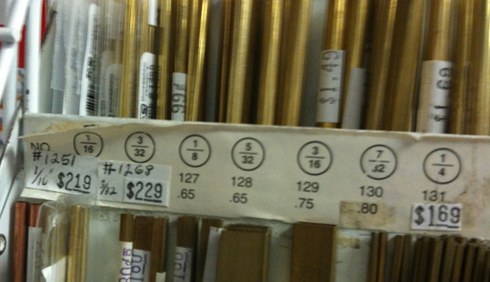
I’m currently collecting parts and materials for a small-scale functional prototype. I’ll be using 6″ diameter wheels up front and from that I’ve been scaling down dimensions from my design graphics to match that proportion. Presently, my small-scale prototype will be 22% the size of the real deal. That’s not quite quarter scale, and should be plenty big enough for me to build most components in about the same way they’d be built in full size. If I also scale my materials as much as possible, it’ll give at least some idea of structural rigidity (although not material rigidity). More importantly it’ll hopefully reveal the majority of mechanical complications. I’m going to use brass tubing because it’s inexpensive, readily available, and I can solder it together similarly to how I’d weld the real thing out of steel. I can also easily bend curves and other complex shapes without too much effort

So at 22% scale, my equivalent brass tubing sizes are as follows:

1″ steel tubing (the majority of the structure) = 7/32″ brass tubing [rounding to 1/4″]

1-3/4″ steel tubing (the heavy bits of the roll cate) = 3/8″ brass tubing

1/4″ steel plate = 1/16″ brass plate

These materials should be lightweight enough to be easily workable. Once it’s all soldered together, it ought to be pretty sturdy. I’ll be able to find small bearings, bushings, and other hardware at the local R/C car shop. Now that I have both a working band saw and a drill press, I should be able to fabricate pretty much anything at that scale. I wonder if I could even mill parts on my dremel press from solid brass if I take small bites. We’ll see.

How to make a fiberglass mold

Here is an eight part series on the basics of molding and casting in fiberglass. I’ve done a lot of this before, but it’s very good to have a refresher. Casting key FG parts for Project Streetliner is going to be a major part of construction. I’m thinking that perhaps I need to go ahead and shell my bicycle prototype velomobile-style when the time comes. Although, that’s kind of awesome — if I take my time and do that prototype correctly, I’ll actually have two vehicles when this is all done. One for the highway, and another for the bike path. That has me thinking about electric assist…