Roll cage standards, weight savings and a major oversight

Earlier this week I scrounged around online for SCCA safety cage standards and found this PDF. The information was not only interesting, it was intensely helpful. But before I get into all of that, though, let me say this. It is not my intention to follow the every letter of this standard. I’m simply using it as a guide.

It’s a lot of spec to pour through for the casual reader, so here are the highlights as they pertain to this project.

  • Must be of one of two designs: A high roll hoop (over the windshield), or low roll hoop (over the steering wheel).
  • Must be protect from roll over, impact with an obstacle, and impact from another car.
  • Must be able to support the weight of the vehicle if overturned
  • Must be able to withstand the forces withstood should the vehicle go sliding on the cage
  • Head restraint is mandatory and must prevent whiplash as well as prevent the driver’s head from striking the main roll hoop. Depending on what seat you use, the head restraint may or may not be required to be physically tied into main hoop.
  • Any forward bracing from the main hoop must be padded if the driver’s head is able to contact it.
  • Neither the cage nor the chassis can have an aerodynamic effect that creates lift.
  • The cage must prevent engine intrusion into the driver compartment.
  • Minimum tubing sizes for mild steel for vehicles under 1500 lbs: 1.375″ x .095″
  • The main hoop must be one continuous piece of steel, can have no more than four bends, those bends cannot total more than 180º, and the radius of those bends must be more than 3x the diameter of the tubing
  • The front hoop must also have no more than four bends
  • Rear hoop supports (cross bracing) must be straight
  • The rear hoop, if possible, should go all the way to the floor and all joints should be reinforced by gussets or sheet metal webbing
  • The main hoop must have at least two braces extending to the rear, and two to the front, attached no more than 6″ from the top of the hoop, with an angle of at least 30º
  • The front hoop requires two braces to protect the driver’s legs
  • Side protection should include at least two tubes connecting the front and rear hoops across all door openings
  • The roll bar must be able to withstand stress loading of 1.5x laterally, 5.5x longitudinally, and 7.5x vertically where x is the minimum weight of the car.
  • The race seat must be firmly mounted to the frame, and the back of the seat must be tied into the main hoop or its cross bracing unless the seat is specifically designed to be unbraced.
  • The main hoop cannot be less that two inches above the driver’s head
  • A straight line drawn from the top of the main hoop to the top of the front must pass over the driver’s head.
  • The main hoop must be at least 15 inches wide where attached

There’s a lot there, but there are a couple of things that had a really profound effect on my design. The first is the minimum tubing size of 1.375″. I’d been doing all my weight calculations on 1.675″ tubing and by scaling down to this standard, the estimated weight of my safety cage goes from about 130 lbs to about 80 lbs. That’s a huge difference, especially for a vehicle this light and with the efficiency ambitions that I have. So that’s a win.

The second significant standard wasn’t so kind. It’s this one:

A straight line drawn from the top of the main hoop to the top of the front must pass over the driver’s head.

Here’s what that looks like in my current design:

The problem here is obvious. I’m less concerned about the standard itself than what the standard is meant to prevent. Namely, the vehicle landing on my head. There are really only two solutions to this, at least that I can think of. Either both the front and rear hoops get taller (which kills my streamlining and visibility), or I’m going to have to brace across that gap in a way that clears my head. So I took a page out of the off road buggy book an designed a pair of curved A-pillars to connect the front and rear hoops.

What I’ve rendered here is incomplete, in the sense that there will be a lot more cross bracing than is currently showing. For simplicity’s sake, I’ve kept this rendering to just the main hoops and cross members (plus the door). This change doesn’t really have any impact on the body shape or my aerodynamics, thankfully.

What these new A-pillars do effect, however, is the canopy design and entry/exit. While the struts themselves may indeed bolt in and out in the end, they won’t swing over with the canopy as it previously worked. In fact the whole removable canopy idea is kind of out the window at this point, I think. Instead, there will likely be more of a t-top arrangement where the side windows and perhaps part of the roof are removed and stowed. That, or perhaps just go Jeep-style and do zip-out covers that are heavy canvas or nylon with polycarbonate windows suspended in the fabric. This does afford an opportunity for an elegant permanent windshield, however. By curving the A-pillars in as well as up, that compound curve (which will be a bitch to fabricate, but worth it), should make getting in and out (via the door) easy as any normal car, if not easier. And at just over an inch in diameter, they shouldn’t impede my visibility. While perhaps not as mean looking as the full canopy was, this new design is mean looking in a different way, and a whole lot safer. I’ll take that.

Concept finalization


I’m gaining more and more momentum when it comes to finalizing the Streetliner concept. I’ll be putting together a more comprehensive full spec post later, but for now, here’s an update on the exterior design. I feel like I’ve finally found the art deco mojo I’ve been looking for all along. While the updates are subtle from concept Echo, a lot has gone on under the skin to help me arrive at this, the most finalized shape to date.

Most significantly, I realized that my seat and human analog were actually too large, as was my representation of the ATV drivetrain — each by about 20%. This meant that I could shrink the wheelbase as well as the cabin size by significant amounts. I had previously been concerned about the front to back balance of a rear-engine design, but these new proportions make it seem like it won’t really be an issue.

I accounted for a “jack shaft” that will inevitably be required to get proper rear wheel sprocket alignment. It also allows me to more easily monkey with the final gear ratio to the rear wheel. Additionally, it allows for easy fitment of a belt-drive, which will require much less maintenance than a conventional chain. I reworked the rear suspension in such a way that I can still get a lot of travel, but I don’t have to build a whole subframe back just to intersect the shocks. I’ve essentially just extended the rear swing arm. What may not be obvious from the side rendering is that there are arcs involved that would allow the shock(s) to be centerline instead of at either side of the swing arm. In the rendering there’s a ghosted wheel showing the full 6″ suspension travel. The jack shaft is inline with the pivot for the rear swing arm, which should keep things nice and smooth.

Front and rear, I’ve simplified a few things, and added others. Most noteworthy is the addition of a rear window, which is something I hadn’t had in the concept previously. The view won’t be great, but it’ll be much better than nothing. I’m thinking that rather than a rear view mirror, I’ll utilize a rear-facing camera built into the high brake light assembly. That will have a better view than any mirror system that would conceivably work (although I did have a hilarious rear-view periscope idea). I also abandoned previous modern-style brake lights and turn signals in favor of more conventional round lights. This is actually more in line with the classic design language from cars in the eras I’m trying to emulate. In the end, I’ll be somewhat limited in what I can find off the shelf, but standard round light will actually look better, in my opinion. I was designing those other signals and lights almost in a vacuum. I think they were cool looking, but in the end, such modern details would look out of place in this shape, I think.

Lastly, I finally paid some real attention to the front cross-section of the vehicle. I was able to resolve the shape such that I now have a completely flat front suspension parallelogram, but still enough body and wheel clearance to get about 40º of tilt out of the vehicle before the wheels bind or the body touches the pavement. I know for a fact that I’ve never put 40º of lean on any two wheeler I’ve ever owned, so this ought to be plenty. What’s more the cabin ought to be pretty comfortable, with little compromise toward comfort. It should just fit me, but with some reasonable room for comfort.

So let’s hear it. What does everybody think? If you’ve got other ideas, now is the time for them. As far as I’m concerned this is the design I’m moving forward with. I’ll hopefully be starting a small scale foam shape prototype today and I’ll share progress as soon as there is any. I’ll also be doing some small-scale safety cage models, likely in brass tubing, for structural testing and evaluation by people who know more about this crap than I do.

Safety cell construction: looking for your thoughts

I’m getting to a point of critical mass with this project. I’m feeling like it’s truly time to “shit, or get off the pot” as they say. While I have no doubts as to my desire to truly see this project happen, I’ve been distracted of late and have a few lingering things I need to figure out. So I’m throwing those topics out for discussion to keep them moving forward.

Firstly, I need to finalize the broad chassis design when it comes to the safety cell. One of my major design criteria for this vehicle is that the driver be completely protected, much like a race car. Obviously weight is a consideration, but every bit of stiffness gained from driver compartment reinforcement is also stiffness gained for better handling. I feel very finalized in my plans to have front and rear sub frame assemblies that hold the front suspension and engine respectively. These would be tube steel and would bolt onto the safety cell in some manner of catastrophic break-away fashion, regardless of the safety cell’s construction. The question then remains of simply which method of safety cell construction to adopt. Here’s what I’m considering:

Steel tube roll cage — This would be similar to a rock crawler, drag racer, or any number of purpose-built oval track race cars like dirt track or even NASCAR vehicles.

Pros:

  • Relatively lightweight at approximately 100-150 lbs.
  • Very sturdy.
  • Lots of known quantities and standards from organizations like the NHRA.
  • Relatively easy to construct and customize.
  • Reasonably inexpensive.
  • Provides structure for the chassis as well as protection for the driver.
  • Very easy to just weld things onto it or cut things off of it.
  • The thickness of the safety cell could be less than 2″ , which would help keep everything low-profile.

Cons:

  • Very rigid geometry in terms of shape. Complex curves are really hard.
  • Requires some extra equipment (welding rig and pipe bender).
  • Not as lightweight as some alternatives.
  • Provides only stiffness — no energy dispersion.
  • Would need to be jig built in order to prevent heat warping.
  • Would have to create separate inner cockpit lining and separate outer body shell that would attach inside and outside of the cage.

Composite safety “tub” — This is the kind of safety cell used by may alternative vehicles like the Aptera and is based on F1, Indy, and even high speed race boat designs. It’s also comparable to many of the structural construction techniques used in making high performance small aircraft.

Pros:

  • Very lightweight and rigid.
  • Can be made in any shape.
  • Inner surface can be the cockpit lining and even be contoured to make up the seat.
  • Outer surface can literally be the body shell, so no body attachment necessary and weight/complexity savings in unifying the body with the structure.
  • Can be constructed with simple tools for shaping foam and then laying the FB or CF cloth.
  • In an impact situation, the layers of composites and foam would not only provide protective rigidity but would actually absorb a lot of energy.

Cons:

  • Fewer known quantities in terms of rigidity and real-world safety (although that information is probably available through F1 and other sanctioning bodies).
  • Could be more difficult to adjust it on the fly if a big change was needed after it was made.
  • Need to do a cost analysis, but it might be slightly more expensive (only because steel is actually pretty cheap). Not sure how much that much foam and FG and resin will cost.
  • Will be thicker (possibly 4″-6″ inches thick), which could create clearance issues during lean and general bulk

Aluminum and fiberglass monocoque — This is an idea I had yesterday after a brief visit to the EAA Airventure Museum. The idea would be to utilize flat, machined aluminum bulkheads and ribs that interlock at right angles to each other. Then I’d fill the gaps with foam and fiberglass a skin inside and out. Put another way, it’s the F1-style safety cell, but instead of just being solid foam, it’s got aluminum bulkheads and bracing throughout.

Pros:

  • Stiffer than the all-composite cell, but likely still lighter than the steel tubing cage.
  • Inner structure would add a lot of stiffness, probably surpassing either of the other two designs
  • Flat bulkhead designs mean that all the truly structural components could just be water-jet cut and then put together like a kit. It’d be self-aligning and could just be MIG welded at the joints with an aluminum-core wire.
  • It would provide solid metal anchor points for things like the seat, harness, and the subframes front and rear.

Cons:

  • Heavier than the all-composite cell
  • CNC work required to do it right. It wouldn’t be something I could make correctly myself. That means expense both in programming and machine time.
  • Might simply be overkill, although over-engineering the safety cell isn’t really a bad thing, now is it?

My favorite option at the moment is the third concept. Perhaps just because it’s the newest idea, but there does seem to be a lot of elegance to the interlocking aluminum bulkheads. I’m looking for input. Give me your thoughts. What have I overlooked? Is there a structural engineer in the house?


More ATV thinking

So the seed planted by Aaron to use ATV drivetrain is growing into something cool. On twitter, @blalor suggested Honda’s line of TRX sport ATVs. They’re 2WD, chain-driven, EFI, and possibly perfect. I keep eyeing the 400 and 700 models. Both are single-cylinder “thumper” motors with a wide bore and thereby tons of available low-end torque — which will come in handy once I gear it up. I wish Honda were more forthcoming with horsepower numbers, but I’m not finding any. That’s but a detail at this point though.

This ATV setup lets me do a couple things. It lets me run a larger motorcycle wheel and tire on the rear. That gives me higher gearing than both the scooter drivetrain and the original ATV setup by default. Rear sprockets are very easy to change, and this gives me lots of latitude in adjusting the final gear ratio of the drivetrain without touching the actual transmission. Reading up on the TRX specifically, there are aftermarket solutions for high performance exhausts and apparently it’s pretty straightforward to re-map the EFI. That should let me tune a “butter zone” where the motor is at it’s most powerful in its high ranges and it’s most efficient in its low ranges. That way under acceleration, I’ve got plenty of power, but while cruising, it should just bump over and sip fuel. What could be even sweeter is if I could set up a switcher box of some sort that would let me pick between two EFI maps on the fly. One for power, the other for efficiency.

One thing I was very curious about was how the chassis would need to change in order to incorporate a separate engine and rear swing arm. One of the simple beauties of using a scooter drivetrain is that the engine, transmission and rear suspension are all basically one big piece. This is simple, but it isn’t automatically light and there’s no reverse gear option. So what happens when I swap out for an ATV/motorcycle rear end?

I found some reference images of the TRX700xx powerplant and rendered up a quick cross-section. This image compares the original concept Suzuki Bergman powerplant with the TRX. Everything is approximate, of course. The other key shift in this rendering is that I dropped the seat height basically to the floor. This to decrease the forward cross-section that much more. The trade-off is adding about 10″ to the wheelbase between the two changes. This puts the length at about 3″ longer than the wheelbase of BMW 3-series coupe. Not bad, considering it’ll present about 1/3rd the frontal area.

The next question was obviously what does this do to the body shape? Making the hood line lower and the tail longer did some neat things for the side shape of the body. I especially like how that big wheel looks in the rear. The overall effect is really slick. I can’t wait to model this in foam or pine and see what it looks like in 3D. More to come.

Entry and exit: its ramifications on exterior design

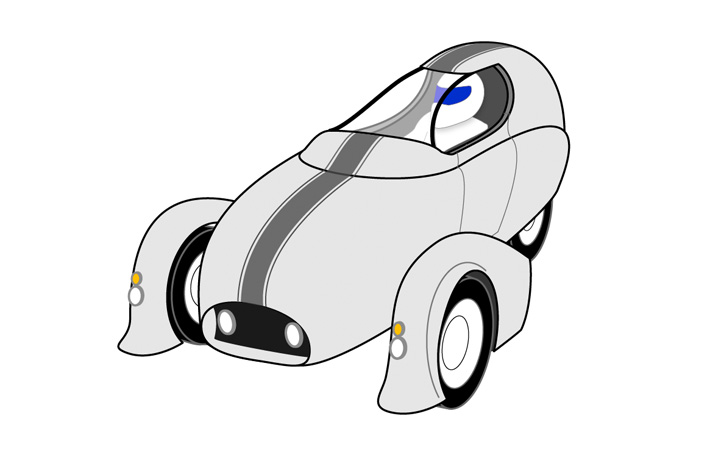
There’s been a lot of activity on the Streetliner drawing board this week. If you’ve been following along, you’re familiar with the shape above. This ’30s era race car inspired shape is what I’ve been showing people when they ask about what I’ve got in mind for this project. I love it, but I knew all along that this shape would inevitably change and evolve.

Likewise, one major aspect of the Streetliner’s design had yet to be worked out in concept: entry/exit. How the hell do I get in and out of the thing? It’s not that entry and exit is terribly complex, but in figuring out a good way to get in and out, it meant big adjustments to the exterior design of the car. So like any design undertaking, this needed criteria.

  • The integrity of the safety cage needs to be maintained as much as possible
  • Getting in and out has to be simple. No folding myself up snaking through impossible openings
  • I must be able to exit the vehicle even if the primary door system fails


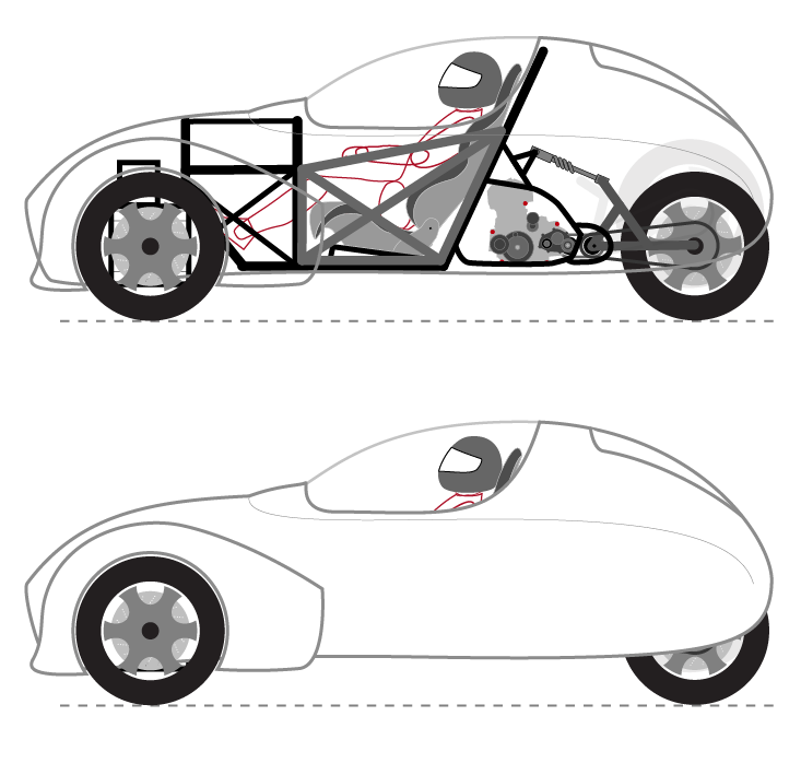
So starting with the current exterior design, a handful of things have been adjusted since I first penned Design Concept Alpha. The overall length increased, the front wheels got larger, the wheel pants got longer and no longer turn with the front wheels. I really like this shape overall. The snout shape of the front end is very pleasing, the rear has a lovely duck tail quality, and I especially like this design because the vehicle looks even better with its canopy on. All of that shape, however, is mated to an underlying safety cage and chassis:

With arches as the vertical pieces, the safety cage design is pretty straightforward. Heavy duty curved bulkheads are connected by heavy duty rails, then everything is cross-braced in a truss of smaller diameter steel. The angled front and rear main plates actually create rudimentary “crumple zones” where impact damage would send the motor assembly and or front suspension components under the vehicle in the event of an impact. This design is structurally sound, but it has one major flaw: how the hell do you get in and out of the thing? The height of the cockpit opening lip is right at 36″ in this design. I’m pretty tall, but that’s still quite a height to throw a leg over while getting in and out. I also realized that I’d only given myself a 24″ deep opening front to back. I’m not a whole lot narrower than that myself (it’s winter weight, I swear!). So the practical concerns of getting in and out of a high, narrow opening are pretty significant. But even beyond entry acrobatics, with such a narrow opening, I wouldn’t be able to see my hands or any cockpit gauges. That top opening needs to grow and dammit, I need a door. The tricky bit is how do I add a door without compromising the safety cage?

One thing at a time. I added an approximation of the front suspension “box” and see where and how that should tie into the frame. I lowered the bottom rails to tie in to the front and also simplify the rear subframe where the mono-shock would attach. I also moved the main roll hoop back just slightly where previously it was implied that it would overlap my shoulders. Upon further reflection, I realized that this being a single seater, I only need one door. Even though my diagrams here show the opening on the left side, I think I’m going to opt for the right side having the door. Since the majority of motorcycle accidents involve people violating your right of way from the left, it makes sense to me to leave the left side solid. That written, the underpinnings of the door as I’ve envisioned it are as substantial as the major parts of the cage. That way when it’s closed and latched, the door becomes part of the safety cage. I like to think of it like the harness that comes down and locks in when you get on a roller coaster. Solid. Also, thinking about an impact scenario, that’s a force into the cage, so if the door is structurally captive against being pushed through the opening, it ought to be as good as solid. With the door opening on one side of the vehicle, the canopy (when attached) could hinge along the opposite edge — making for a very easy time getting in and out.

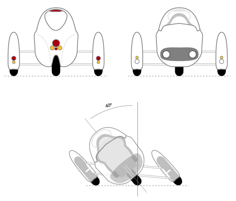
With that adjustment made to the frame, the body shape needed adjustment, as you can see below. The opening needs to be increased to meet my design criteria for being able to exit the vehicle in a pinch through the top without using the door. The bottom profile of the body shape also needed to be adjusted to account for the front suspension box.

Now with the shape updated, I like it even more. The larger top opening not only gives the whole vehicle a better proportion. It looks smaller and more trim overall. Before now, with the length being about that of my MINI (which I know, isn’t exactly big), the Streetliner has looked strangely large. Now it looks much more like the race car cabin scooter it was always meant to be. I also reshaped and shortened the wheel pant to account for the door opening.

I really felt like the new shape came into its own with the canopy in place. Not only was it less bubble-shaped, but it completes the curve created by the tail. I can also imagine much better visibility and comfort within the cockpit. That led me to consider some alternate front end shapes. One of which was the sloped, Ferrari GT-style nose. It would borrow its hood scoop aesthetics from a different era than I’d previously been thinking, but I really like it. Forward visibility would be better and overall aerodynamics might be a tad stronger with this sloping approach.

All that remained at this point was to add some visual interest to these basic shapes. This included sculpting the rear and adding a sort of LeMons-style front lip to the wheel pants. I really don’t want to overlook subtle details throughout the shape. Sure, a perfectly smooth Velomobile kind of shape is terrifically aerodynamic, but without at least some minimal sculpting, I think the shape would look like it were stuck in the ’70s and just generally unfinished. These details will surely evolve as the project progresses, but I’m loving it so far.

As I look back on the progression, it’s amazing how much influence a little thing like a door can have, but all for the better! This shape still has a lot of classic Italian sensibility, a lot of race car mojo, and plenty of salt flats shape credibility. As much as I love the ’30s sensibility of Concept Alpha, I like this even better. But more than that, I’m glad to have another big piece of the conceptual design puzzle in place.


Scale sizes for brass tubing

I’m currently collecting parts and materials for a small-scale functional prototype. I’ll be using 6″ diameter wheels up front and from that I’ve been scaling down dimensions from my design graphics to match that proportion. Presently, my small-scale prototype will be 22% the size of the real deal. That’s not quite quarter scale, and should be plenty big enough for me to build most components in about the same way they’d be built in full size. If I also scale my materials as much as possible, it’ll give at least some idea of structural rigidity (although not material rigidity). More importantly it’ll hopefully reveal the majority of mechanical complications. I’m going to use brass tubing because it’s inexpensive, readily available, and I can solder it together similarly to how I’d weld the real thing out of steel. I can also easily bend curves and other complex shapes without too much effort

So at 22% scale, my equivalent brass tubing sizes are as follows:

1″ steel tubing (the majority of the structure) = 7/32″ brass tubing [rounding to 1/4″]

1-3/4″ steel tubing (the heavy bits of the roll cate) = 3/8″ brass tubing

1/4″ steel plate = 1/16″ brass plate

These materials should be lightweight enough to be easily workable. Once it’s all soldered together, it ought to be pretty sturdy. I’ll be able to find small bearings, bushings, and other hardware at the local R/C car shop. Now that I have both a working band saw and a drill press, I should be able to fabricate pretty much anything at that scale. I wonder if I could even mill parts on my dremel press from solid brass if I take small bites. We’ll see.

Surprising weight

I’ve refined my safety cage a bit and done some more research into safety cages used in racing. I found a kit that featured 1.75″ tubing with .135″ thick walls. Running that through the online weight calculator I’d found, that comes out to 2.133 lb/ft. I also did a calculation on 3/4″ tubing of the same wall thickness for use in cross ties and such. Figuring out the length of the tubing in this design, I was able to do some weight calculations:

This is all obviously napkin math, but the result is pretty surprising. If I use the 1-3/4″ tubing for the main structural hoops, then tie it all together with 3/4″ tubing, my entire safety cage and main chassis would only weigh about 100 lbs 130 lbs. This doesn’t include some sub-frame pieces and none of the front suspension components, but still, that puts me well on my way, I think, toward making my < 600 lb design criteria.

Wheel size, wheel pants, stability and leverage

They were apparently absolute murder to ride, but nothing quite says vintage transportation like the Velocipede. The thing I’ve always found fascinating about these is their huge front wheels. The physics of a bike like this must feel very odd compared to bicycles of today. The force of angular momentum of a wheel (the force that makes it want to stay upright and that leans it when you top turn it) is directly proportional to the torque moment of that wheel. Or, said in non physics babble, the bigger and/or heavier a wheel is, the more stable it is when its rolling. It’s kind of an amazing force, when you think about it. The two tiny rollerblade-like wheels of a little razor scooter generate enough angular momentum to hold an adult upright. In larger, powered two-wheelers like scooters and motorcycles, wheel size makes a huge difference in the character of the machine. Scooters have traditionally had much smaller wheels. Most vintage small-frame Vespas had only 8″ rims, while their large frame brothers weren’t much larger at 10″. My modern Vespa has 12″ wheels, but still feels very much like a scooter — agile, and a tad butt-heavy. Motorcycles tend to have anywhere from 14″ to 22″ rims depending on the style. When I test rode a Triumph Bonneville in 2008, what I noticed immediately was that it took about half the speed I was used to in order to get rolling stability. Once moving, the larger wheels and rolling mass of the Bonneville felt so solid — like it was on rails. What would wheel size mean for the Streetliner?

Bigger front wheels
While playing with the proportions and broad strokes design details of the Streetliner this week, I wondered what would happen if I swapped out Burgman-size front wheels for larger wheels from another bike in the Suzuki fleet. The size of the rear wheel is likely fixed because of the shape of the engine/transmission casings. Big wheels up front would definitely give it a stronger visual connection to the old race car designs that have inspired the project. Especially if I grabbed the spoked wheels off of something like the Boulevard S40. But beyond aesthetics, it would make some significant differences to handling comfort, lean feel, and possibly even make the front suspension easier to build. It looks the business though, doesn’t it?

That’s an 18″ rim up front as opposed to the 14″ stock Bergman rim on the rear. It definitely calls back some nostalgic racing mojo. Larger diameter wheels would mean that the front end would take bumps better and have greater rolling stability. It’ll also mean more room inside that wheel for all the tilting mechanicals, brakes, and steering attachments. What it would also mean is that the lower and upper swing arms of the tilting suspension could be further apart — letting me have not only better ground clearance, but deeper leaning on the same distance between the wheels.

If you go back to my initial lean study, I explored the relationship between body height and leaning. With the larger wheel size up front, a couple of good things happen. First, I’m able to spread the swing arms apart, meaning that at the same lean angle, there’s less interference. This is important at both the wheel attachment points and where the dampening assembly will go (the shocks and their connecting structure, which isn’t shown). The more room there is to work in those assemblies, the better. Not only will it be easier to build, but it’ll mean more opportunity for building fine tuning and adjustment points right into the structure.

Stability
The biggest difference may indeed be felt in leaning stability. The greater mass of those larger wheels would mean nearly instant leaning stability. Whenever I see a Honda Goldwing slowly lean its way through an intersection turn, it amazes me that the 900 lbs or so of the Goldwing are able to be held up at such low speeds. The Goldwing has an 18″ wheel up front and a 16″ wheel in the rear, and that’s enough to keep it stable, even at low speeds. With two 18″ wheels up front, the leaning stability ought to be massive. But more than that, having the swing arms further apart vertically, means that the side-to-side forces generated by the wheels when they precess (based on steering input) will not only be greater, but have more leverage on the body of the vehicle.

The one thing I wonder about, however, is what it will do to the driving feel of the vehicle? Greater stability means that it will take more input force on the steering to induce the lean — and that force will grow with speed. That’s a good thing, as you wouldn’t want the vehicle to be all twitchy at 70 mph. I’m not worried about it, I just wonder what the feel will be. I imagine it wouldn’t be much different than a big cruiser motorcycle with the Tilting Motor Works kit installed.

Wheel pants
From the beginning, I’ve envisioned the Streetliner with wheel pants for added aerodynamics and efficiency. This inspired by both ’30s era aircraft like the Gee Bee but also similar projects like the Aptera. Exposed wheels simply aren’t very aerodynamic. Putting a streamlined shroud around the wheels will add effeciency (and look fantastic). However, I’m not exactly sure just how much efficiency is gained. Adding wheel pants will definitely add time and complexity to the build, and at some point I’m going to have to do an aerodynamics study to see how much more efficient the shrouded wheel is than a naked wheel. One thing I have to keep in mind though, is that unless I can put a decent tail on the pants, there won’t be much advantage in the wind. However, that tail will quickly limit how far I can turn the wheels (because the tail of the pants will hit the body). That means a large turning radius, and for a vehicle intended for mostly city use, that’s not a good thing. So if I have to sacrifice wheel pants for the sake of turning ability, that’s a compromise I can’t not make. But I do just love the look of the pants. I hope I get to keep them.